 |
|
Projects: Human Interface Devices
|
|
|
|
are to control comply modules. powered cables. The modules with their displays, key and the like can be mounted behind front panels, provided that appropriate connectors are inserted.
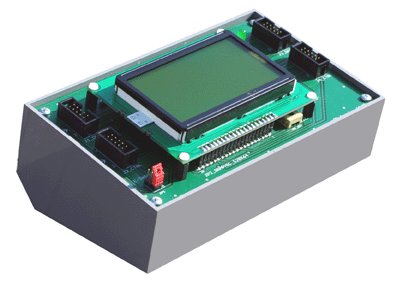
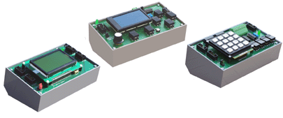
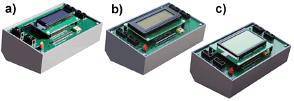
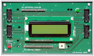
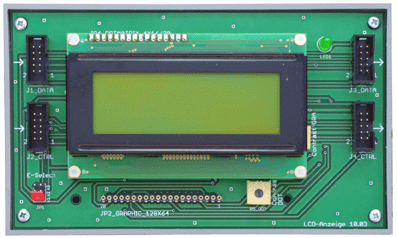
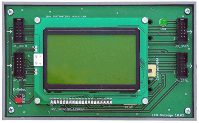
The LCD module 10. The PC board can accommodate three types of industry-standard LCD displays: a) dot matrix, 2 rows; b) dot matrix, 4 rows; c) graphical, 64 • 128 pixels. Up to three modules can be connected to two microntroller I/O ports in a daisy-chain fashion.
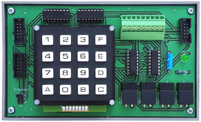
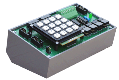
The keypad/input module 10b can accommodate keypads with 12 or 16 keys. Additionally, eight inputs from outside can be attached.
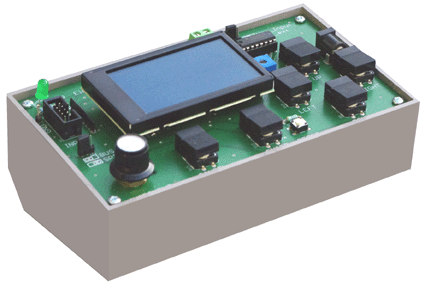
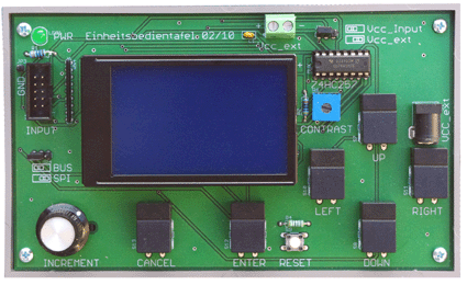
The general-purpose human interface module 02/10. It features a dot matrix display with four rows of 20 characters, 6 keys and an incremental encoder. It requires only one 8-bit-port. to have elementary debugging console.
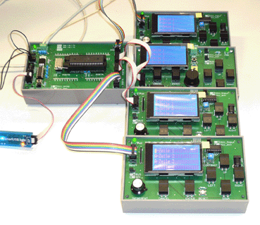
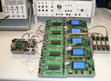
Here four human interface modules are attached to one microcontroller module. Each of the human interface modules is controlled by one of the application programs running in a time-sliced fashion (preemptive multitasking). Bring-up of a digital analog computer. Each of the 6 microcontrollers on the master controller board is connected to a human interface module, serving as debugging console.
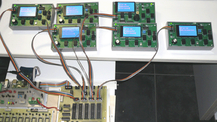
Testing and debugging of an experimental multiprocessor system. Each of the microcontrollers has its own console. The seven-segment displays (rigtht) show, whether the corresponding microcontroller ist still running or has itself hung up. Additional pictures:
|
|
|
|
June 24, 2016 References have been updated.
|