|
|
|
Projects: Microcontrollers and CPLDs - a viable combination
|
|
|
|
For projects, which do not vindicate the cost and development effort of an appropriate FPGA, combining two industry-standard integrated circuits can be a viable solution. It is comparatively easy to design and build PC boards for microcontrollers and CPLDs. The components are inexpensive. It is not that difficult to become familiar with the principles of operation. Microcontrollers can be programmed in Assembler or (for example) C. In many cases, CPLD functions can be implemented by describing their behavior (for example, in VHDL or Verilog (where the differences to C are negligible)). The communication between the functional units can be easily observed (for example, by means of a logic analyzer).
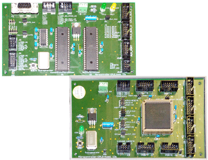
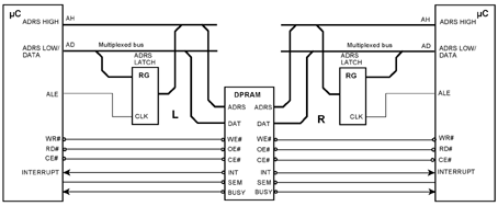
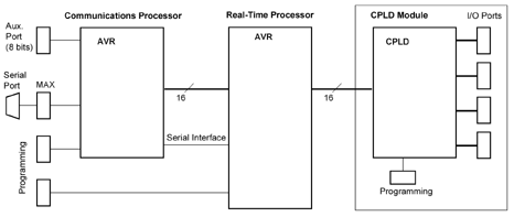
The first project is an educational compound platform, comprising two microcontrollers and a CPLD. The platform is split up in two PC boards. The obvious advantage is, that they can be used independently. One of the microcontrollers is thought as the communications processor, the other as the applications or real-time processor. It can be connected to the CPLD. The CPLD serves as I/O extension or attached support processor. Why two microcontrollers? The real-time behavior must always be deterministic; up to the clock cycle, if necessary. The program in a true real-time processor must not be interrupted or forced to cycle in wait states of unpredictable duration. The classic solution provides two processors coupled via a dual-port memory. In an educational system, absolute performance is not critical. Therefore, both processors can be connected directly to each other. The interface is centered around an 8-bit-bus. An additional serial interface is used for initialization, debugging and the like. The "classic" solution. Processors are coupled back-to-back via dual-port memory:
The simplified structure:
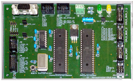
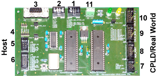
The microcontroller module:
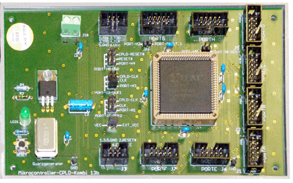
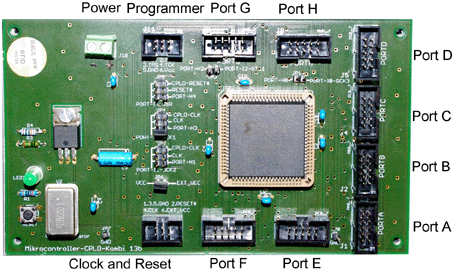
1 - Programming of the real-time processor 2 - Serial port (5 V signalization) 3 - Serial port (RS-232) 4 - Serial port (RS-232) and power 5 - Programming of the communications processor 6 - SPI-port of the communications processor 7 - CPLD clock and reset 8 - Auxiliary port of the communications processor (8 bits) 9 - CPLD selection and control signals 10 - CPLD bus (8 bits) The CPLD module:
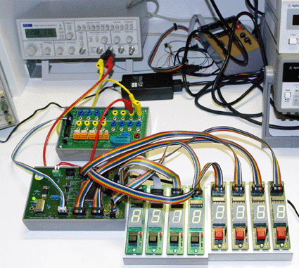
It is connected to the real-time processor via an 8-bit bus interface. The ports A to H are CPLD signals. They have been routed to pin headers to facilitate attaching peripheral devices. Here the CPLD has been programmed to work as time-of-day clock with 0,01 s resolution:
|
|
|
|
October 11, 2014 The web page has been set up. Download the schematic of a microcontroller module Download the schematic of a CPLD module Download a description (in German)
|
