 |
|
Legacy Interfaces (1): Emulating the ISA Bus
|
|
|
|
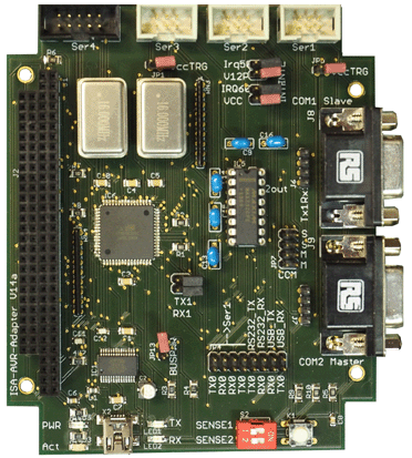
The ISA bus is controlled by an Atmel AVR microcontroller. The emulation has been restricted to I/O functions, because in current applications, only modest I/O cards and PC/104 modules are to be supported.
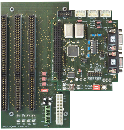
The ISA emulator is a PC/104 module:
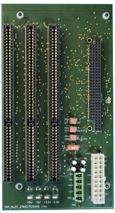
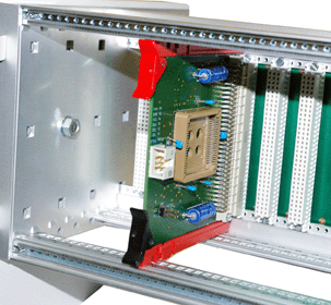
The ISA slot platform allows for inserting up to three vintage ISA cards:
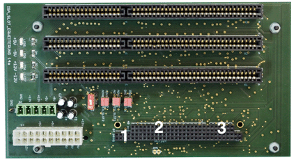
1 - The emulator module supports only 8-but I/O cycles. Hence only the 64-pin PC/104 connector is necessary. 2 - The slot platform, however, supports all ISA signals. So even fully-fledged industrial PC modules can be inserted. 3 - A supplementary connector. It supplies power to the emulator module and carries additional AEN signals. Connectors 2, 3 are to be inserted only if necessary. The ISA slot platform supports geographical addressing via separate AEN signals for each of the slots. When this feature is used, all cards can occupy overlapping or even identical address ranges. Manual address configuration (via jumpers) will not be necessary.
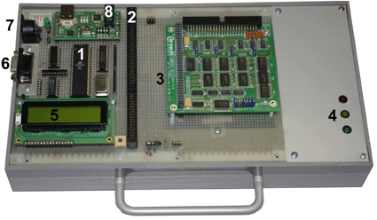
A breadboard implementation of an ISA host based on an ATmega CPU:
1 - CPU 2 - ISA slot 3 - PC/104 stacking area (here with an I/O module) 4 - Power supply LEDs. The power supply is mounted inside the case. 5 - Auxiliary LCD display 6 - RS232 interfaces (two; the connectors stacked one above the other) 7 - PS/2 port (provided to use cheap legacy keyboards as handy input devices) 8 - USB attachment. This piggiback module serves as USB to serial converter and as an AVR programmer.
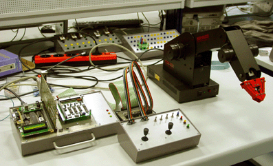
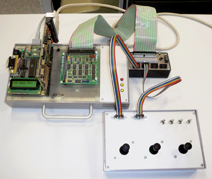
The device shown above is used to control an educational robot. The robot is attached via the ISA card; the operator's console via the PC/104 module:
Some more details...
|
|
|
|
November 14, 2017 ISA Host Controller 15b ISA Base Board 14a Other legacy interfaces:
|
