|
|
|
Voltage-Level Translation in MCU Projects
|
|
|
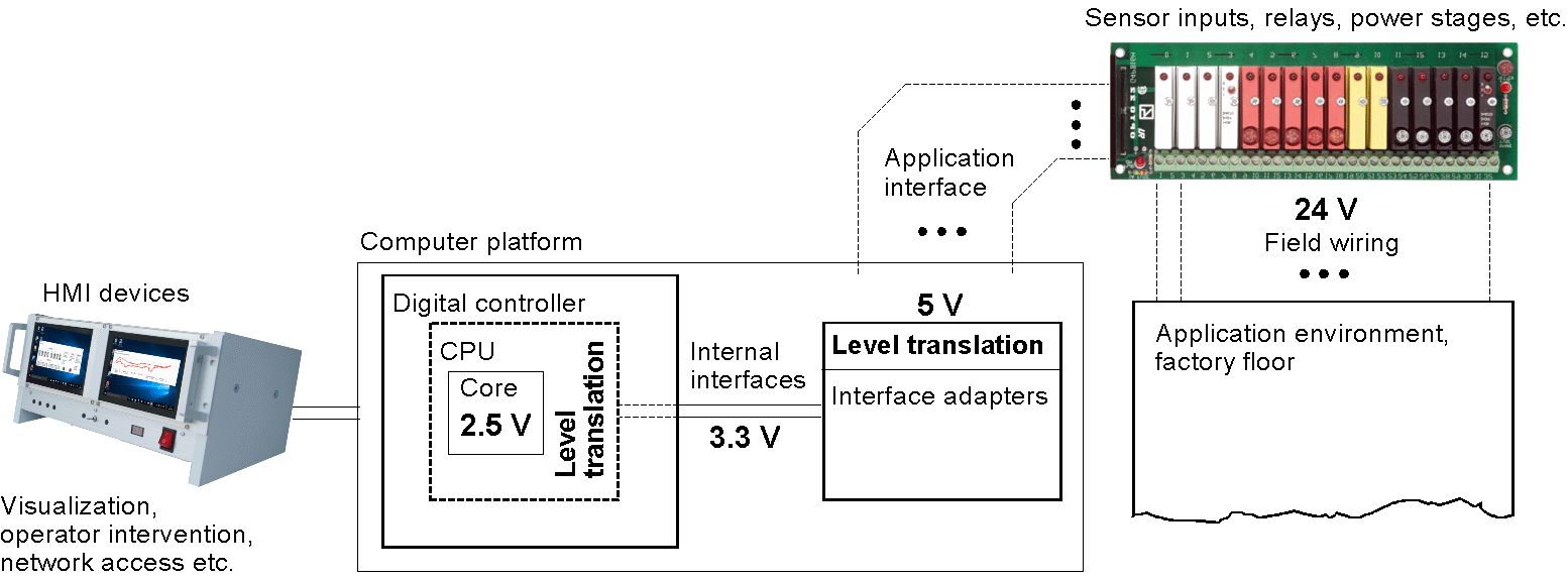
Level-translation between logic and factory floor
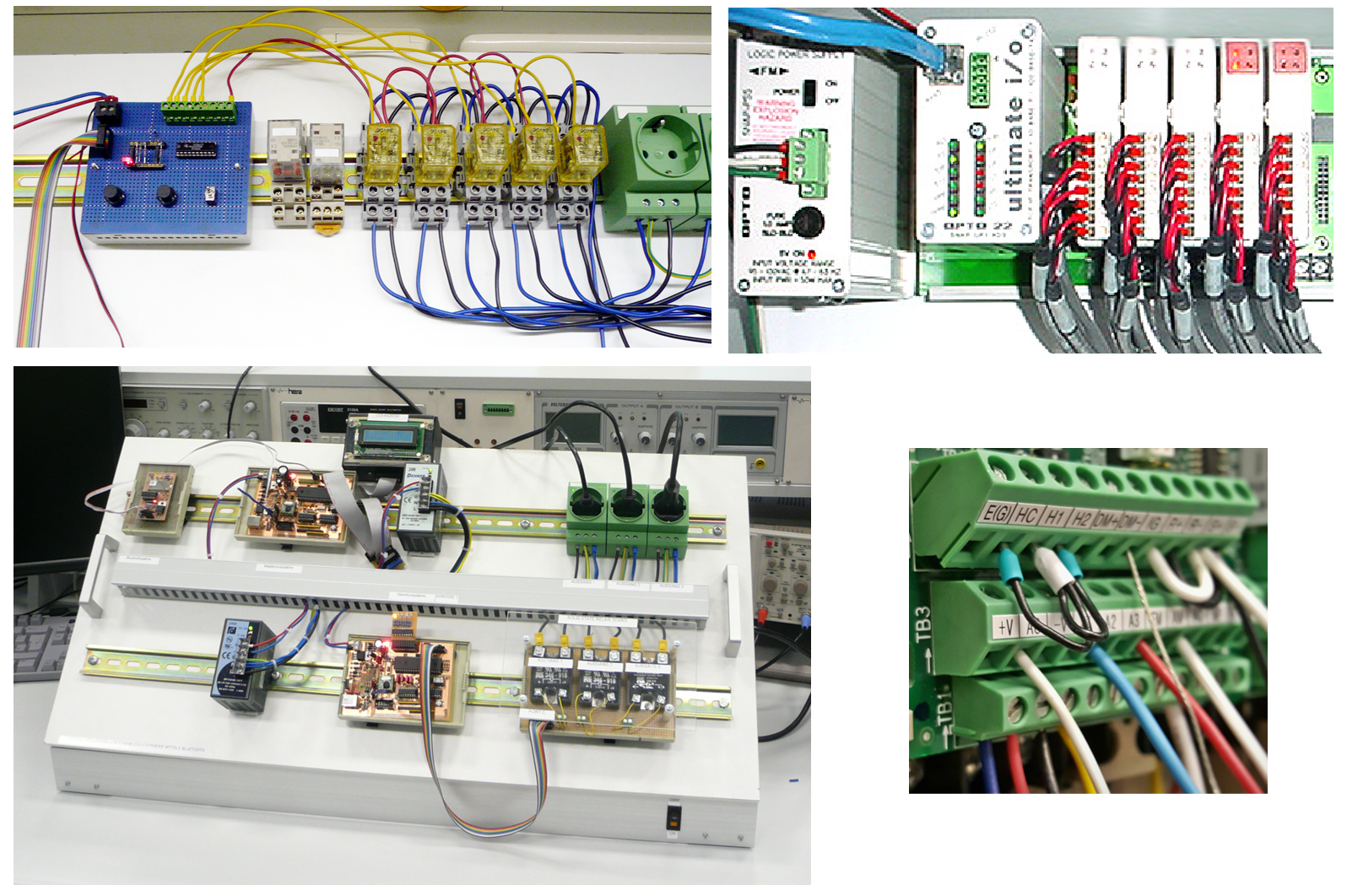
How field wiring is attached. To the left, educational examples are shown, to the right, two glimpses into industrial wiring cabinets.
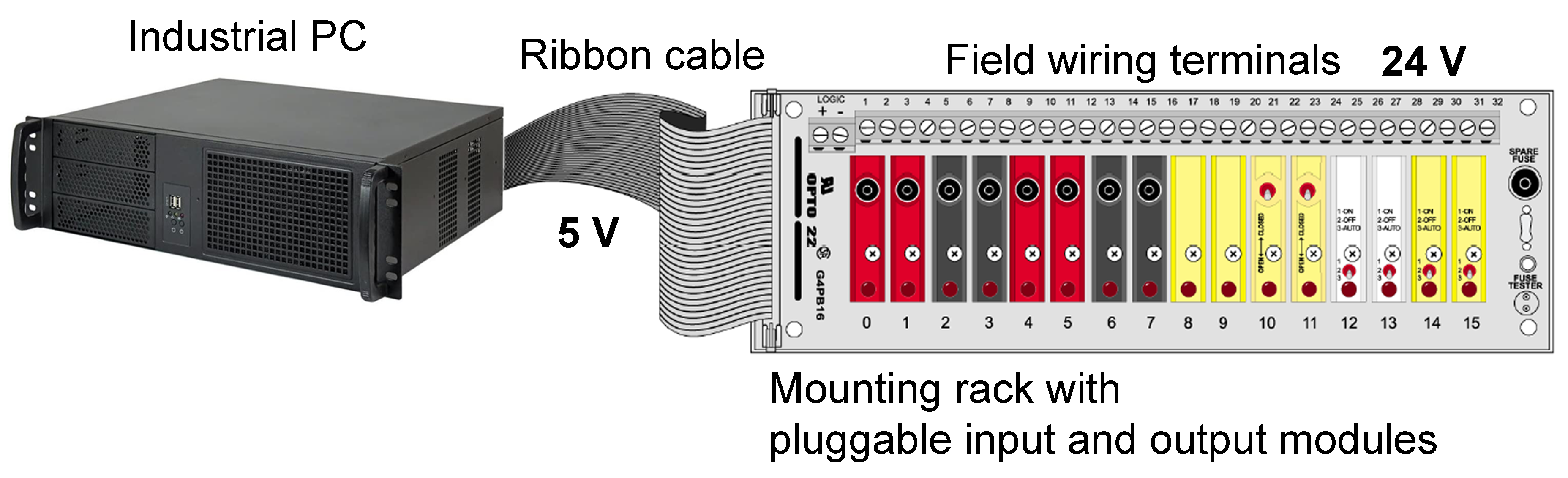
The legacy interface between industrial PCs and mounting racks with I/O modules is a 5-V interface with TTL signal levels.
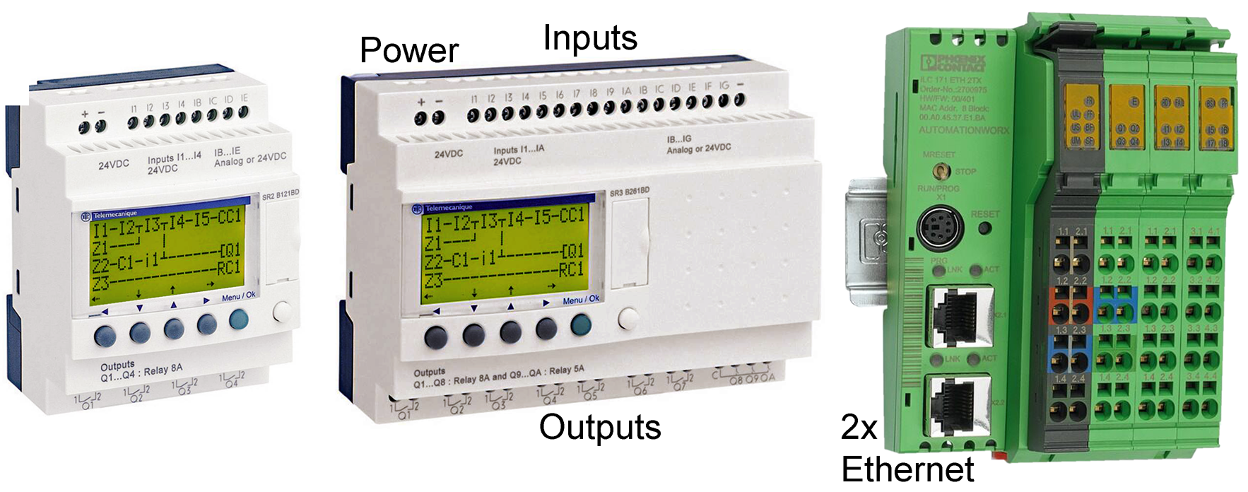
In typical compact PLCs, the inputs and outputs are rigidly determined by design. A limit switch must be connected to a digital input, a relay to a digital output, a sensor to an analog input, and so on.
With regard to level translation, all those digital controllers, as different as they are, may be represented by one block diagram. The main difference is only in packaging or compactness, respectively.
Translating voltage levels may be required on logic PCBs, too. Our example is an educational module based on an Xmega microcontroller. Its supply voltage is 3.3 V. I/O signals are translated to 5 V and, to support an RS232-Interface, to ± 9 V. A particular challenge was to drive a bidirectional 5-V data bus.
|
|
|
|
Download the Internet Addendum to the CC article 24-V microcontrollers and CPLDs
|